
The Aleph Light engine consists of a threaded and anodized Aluminium heat sink (E-Screw),
a nickel plated brass can for hosting the converter board (ES-Can), the converter board itself,
lead wires, an emitter PCB and a Luxeon LED.
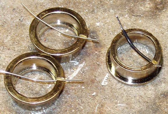
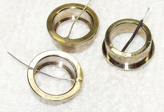
A ground or (-) lead needs to be soldered to the ES-Can prior to assembly. This lead can be
soldered to a groove cut or filed into either the forward or rear lip opf the can or a small hole
drilled into the side of the can. The builders tools as well as nature of converter board will dictate
the best placement of the ground wire. Below, ES-Can's are shown with two possible ground wire
locations, prior to soldering and after being "cleaned up":
It is very important to plan the wire leads to the LED as well as the ground wire and test with dry
fitting prior to any bonding or potting. There is a milled channel in the bottom of the E-Screw
which can be oriented, if needed for allowing clearance of the ground wire if it is attached at
E-Screw end of the can. In the image below, if you look carfully, you can see that the converter
board will be glued into the ES-Can in such an orientation that the soldered ground wire will be
located below and in line with the milled slot in the bottom of the E-Screw. For reference when
looking from above, the milled slot is in the same radial angle as the milled "drive" notches on
the top of the E-Screw. In the image below, a black mark on the lip of the ES-Can is to indicate
where the red + LED lead will be oriented when the converter is glued down onto the shoulder
within the ES-Can. A crazy glue is good for this bond.

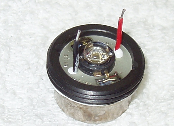
The converter is glued down into the ES-Can and after the adhesive sets, the ground wire is
soldered to the converter and any open vias are filled with solder (if one remembers) so that
epoxy won't weep out of them during potting. In the picture below, the ground wire has been
soldered to the converter. The tail will be trimed and a solder ball will be added to the anode
contact. There is one open via that might have gotten filled as well.

The converter in can is ready for assembly but the LED needs to be bonded to the E-Screw first;
at least this is my prefference.
***********
To install the LED, the LED emitter PCB is first placed in the front bore of the E-Screw and the
lead holes are lined up with the holes through the E-Screw. The E-Screw is then screwed up into
an Aleph head. At this point, I use Arctic Silver epoxy and place a small drop and spread it on the
LED mating surface of the E-Screw.

The LED is then placed down onto the E-Screw:

The LED is roughly centered by eye with care given to the emitter leads ligning up with the
solder pads on the emitter PCB. A reflector is then dropped into the head and some type of non
scratching probe or tool is used to center the LED as well as force it down to press out excess
epoxy. I use a clear acrylic rod that I have machined a concave recess in the end of. This aids in
fitting over the LED lens and makes moving the LED easier. The tube section of a plastic ball
point pen can also be used.

Once the LED is bonded to the E-Screw, it can be removed from the head and at this point, I
pre-solder the LED leads down to the emitter PCB. I also pre tin the lead wires that will be
soldered here to these points. I have found that if the LED leads are trimed to a length of 3/4"
above the surface of the converter board, they are a good length for final attachment to the
emitter PCB. I have a small, flat blade screwdriver that I have notched to act like a "snake
catcher" in managing the LED lead wires and forcing them down in contact with the emitter PCB,
at which point I reflow the solder on the PCB as well as the tinned lead wire and effect a soldered
connection. Now that the E-Screw is sporting the LED and the ES-Can is host to a ground
connected converter, it is time to pot and join the two. I use Arctic Alumina epoxy for this
process. I fill the can to a level that would be even with the sluc on the bottom of the E-Screw that
drops into the ES-Can's interior. I also fill the milled slot on the bottom of the E-Screw with
epoxy. This filled slot, when cured, provides a raised "shear section" when bonded with the
epoxy in the can and this will allow for torque on the can in installation or removal of the Light
Engine from the head.

If you have gauged the proper amount of epoxy, when the two components are joined and
pressed together, some epoxy will come out of the lead wire holes. Excess can be removed with a
toothpick as the two parts are joined and pressed together. Another method of potting is to bond
the two components ahead of time and a hole can be drilled through the E-Screw to accept a
syringe nozzle and the poting material can be injected until it is seen to come up into the lead wire
holes. This latter method is better if a series of these Light Engines are to be done at the same
time.
After the potting material has cured and the LED lead wires soldered to the emitter PCB, the
Light Engine is ready for installation into the head.
Although the LE can be installed from the front end of the head, it is best to have the reflector
and window already installed in the head and to screw the LE into the head from the back side. It
should make contact and be snugged against the reflector at the moment that the rear lip of the
ES-Can is flush with the back face of the head. In the case of using a 5W LED where a shim will
be placed between the rear of the reflector and the face of the E-Screw, the LE will need to be
forced further into the head which in turn will force the reflector into the interior of the window
sealing O-ring. If the LE is driven too far into the head, the battery tube will not make a good
ground contact with the ES-Can lip and the light will not function. If the LED is driven at a high
current for extended periods of time, thermal grease should be used to provide better thermal
paths between some of the components. I would suggest the following:
1) place some grease in the bore of the head that is tight against the reflector. When the reflector
is installed, the excess will be forced down into the head and out of the way. Do not place grease
on the side of the reflector as this would be wipped off and left in the O-ring sealing area.
2) place some grease in the threads of the head deeper than where the battery tube will go. The
excess grease here will roll onto the face of the E-Screw and eventually be sandwiched between
the face and the reflector.
Below, is a picture of a BB LE installed in an Aleph 1 head. You can see the external ground wire
used in this build:
